

SmartClass ORL-85
SmartClass Fiber ORL-85 Inspection-Ready Optical Return Loss Meters
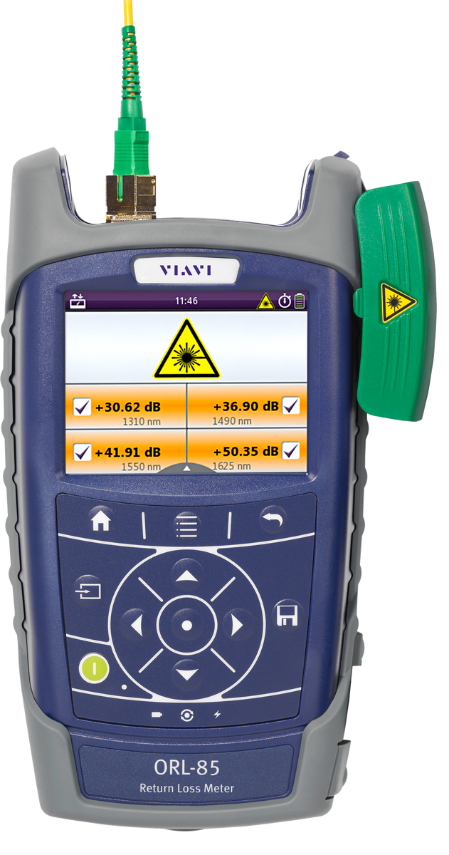
The SmartClass Fiber ORL-85 combine optical power meter (OPM), light source (OLS), continuous wave return loss meter (OCWR), and connector inspection in one compact instrument.
Optical systems with high-speed lasers, analog transmission (CATV), or Raman amplifiers require high return loss for maximum performance. Furthermore, optical return loss measurements can be used to prove that an installation was completed carefully and accurately; for example, they can show that the optical connectors were inspected and are clean. The ultra-sensitive power meter combined with stabilized light sources enable up to a 70 dB measurement range.
The angled single-mode test port (APC) guarantees highly accurate return loss measurements without requiring external termination for up to 50 dB return loss measurements.
Benefits:
- Complete jobs faster, correctly, and on time—right the first time.
- Automated pass/fail fiber inspection analysis with the optional P5000i microscope.
- Compact, rugged, weather-proof design.
Applications:
- Measurement of optical return ross.
- Measurement of optical power (absolute and relative).
- Measurement of optical insertion loss.
- Inspection of optical connectors (IBYC).
Key Features:
- Battery-operated field-portable optical return loss meter with an 1260 to 1650 nm measurement wavelength range (1 nm incremental setting) at the power meter, multiple wavelengths at the source and return loss up to 70 dB.
- Interchangeable optical adapters (Senko) for FC, SC, ST and LC optical connectors.
- 3.5-in color touch screen with integrated stylus.
- Individual threshold settings for power and loss pass/fail analysis.
- Fiber inspection and test results storage with time stamp.
- Data transfer and remote control via USB or Ethernet interface.
- Auto-lambda and multi-lambda test functions.
What is Return Loss?
Return loss is the loss of power in the signal returned/reflected by a discontinuity in a transmission line. This discontinuity can be a mismatch with the terminating load or with a device inserted in the line, and is a measure of how well devices or lines are matched. If the impedance match is good, all the energy will be transmitted through and nothing should be reflected.