

Vector Network Analyzer operation
A VNA measures impedances and gains at high frequencies. Since it measures both the magnitude and the phase it is called a Vector Network Analyzer.
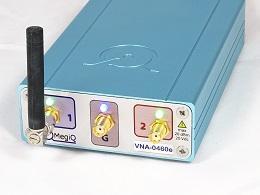
VNA 0460e 6GHz Vector Network Analyzer One Port MeasurementA measurement typically consists of a sweep over a range of frequencies and the results are usually frequency response curves.
Overview
A VNA measures impedances and gains at high frequencies. Since it measures both the magnitude and the phase it is called a Vector Network Analyzer.
A measurement typically consists of a sweep over a range of frequencies and the results are usually frequency response curves.
One-port measurement
Measurements can be done on one-port devices such as antennas and circuits. To do this the VNA will transmit a signal on a port towards the DUT, and at the same time receives the signal back from that port. From the measured receive signal the VNA can calculate the impedance connected to the port.
Two-port measurement

A VNA can also perform measurements on two-port devices such as amplifiers and filters. In this setup the VNA will do the impedance measurement on two ports. In addition, the signal is also sent through the DUT and the signal is measured at the other port. This is a measurement of the gain, or loss, of the DUT from one port to the other. The gain measurement is done in both directions to fully characterize the DUT.
Multi-port measurement
In multi-port measurements all port impedances are measured and all combinations of gains between the ports. This can result in a lot of measured characteristics.
S-Parameters
The measured DUT characteristics impedance and gain are called Scatter Parameters or S-Parameters. They are written as ‘Sxy’, where x and y are port numbers. If the port numbers x and y are the same, an impedance is implied. If the port numbers are different it represents the gain or loss of a signal from port y to port x.
These are the S-parameters for a two port device:
- S11: Impedance at port 1
- S22: Impedance at port 2
- S12: Gain or loss from port 2 to port 1
- S21: Gain or loss from port 1 to port 2
The impedance S-parameters can be converted to a number of formats such as complex impedance, return loss, forward loss and SWR. These all represent the impedance.
The Gain S-parameters are usually represented as magnitude and phase. The phase can also be represented as a Group Delay which is a dynamic delay characteristic of a multi-port device.
Calibration
 A VNA is usually calibrated to measure impedances and gains at its ports, so you can measure devices that are connected directly to the ports.
In vector network analysis you are usually interested in impedances of components and circuits. At high frequencies almost any length of cable will act as an impedance transformer, thus altering the impedance you actually see. Furthermore at even higher frequencies many cables become lossy, which influences gain and impedance plots.
Luckily these cables act as linear elements and can be normalized-out’ by linear algebra. The software will do this for you, but it should be calibrated with some well known impedances for every frequency of interest before you start the actual measurement.
Therefore before using the instrument you should perform a calibration on the whole set-up, including the cables, connectors, etc. for the frequency range you want to use in your measurement.
The software stores this set of calibration data, and with a temperature stable VNA, you will not have to perform this calibration routine very often.
But, changing cables, connectors or frequency range means that you most renew the calibration. Avoid bending cables too much after calibration.
Calibration and Normalization
The process of measuring the (unknown) test setup is called Calibration. This stores the characteristics of the test setup.
The calibration data is then used during the measurement to Normalize the data to become independent of the test setup and the results are the characteristics of the DUT without the influence of the test setup.
OSLT calibration
There are different possibilities for calibrating the test setup but the mostly used method is the ‘OSLT’ calibration (also know as ‘SOLT’ or ‘TOSM’). For this calibration the VNA software uses these impedances:
- Open: a well defined open circuit end.
- Short: a well defined short circuit end.
- Load: a precision impedance of 50 Ohm.
- Through: for two-port measurement a well defined through connection between the two ports.
During a calibration procedure each of these terminations is connected in turn and the software makes calibration measurements for each termination.
Calibration Kits
For the Open, Short and Load calibration you need calibration elements that define these impedances. Since the whole measurement depends on the quality of these elements they need to be as precise as possible. In addition they need to calibrate at the same reference plane. Also the through measurement needs to be calibrated with a well defined through element.
A set of these impedances for calibration is called a Calibration Kit or Calkit. They can be of different types: SMA Calkit, N Calkit, UFL Calkit, Balanced Calkit etc. It depends on your setup, with which connector type you can get closest to the DUT, which Calkit to use. For small microwave devices the UFL connector is often the most appropriate to use.
To get the calibration more precise the Cal Kit usually comes with a set of coefficients or parameters that can be used by the VNA software to compensate with the calibration element’s deviation.
For test fixtures and PCB based measurements there are usually no coefficients because the measurement gets calibrated through the structure, which is hard to model or characterize. The MegiQ UFL and Balanced Calibration Kit is an example of a Calkit for PCB measurements.