| Mechanical |
| Format |
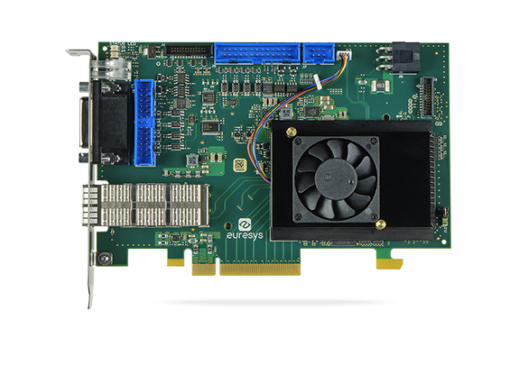
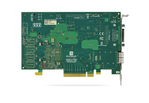
Standard profile, half length, 8-lane PCI Express card |
| Cooling method |
Air cooling, fan-cooled heatsink |
| Mounting |
For insertion in a standard height, 8-lane or higher, PCI Express card slot |
| Connectors |
- ‘QSFP+’ on bracket:
- Enhanced Quad Small Form-factor Pluggable port
- CoaXPress-over-Fiber host interface
- ‘EXTERNAL I/O’ on bracket:
- 26-pin 3-row high-density female sub-D connector
- I/O lines and power output
- ‘INTERNAL I/O 1’ and ‘INTERNAL I/O 2’ on PCB:
- 2x 26-pin 2-row 0.1″ pitch pin header with shrouding
- I/O lines and power output
- ‘I/O EXTENSION’ on PCB:
- 26-pin 2-row 0.05″ pitch pin header with shrouding
- I/O extension lines and power output
- ‘AUXILIARY POWER INPUT’ on module:
- 6-pin PEG power socket
- 12 VDC power input for I/O power
- ‘C2C-LINK’ on module:
- 6-pin 2-row 0.1″ header
- Card to card link
|
| LED indicators |
- ‘A’, ‘B’, ‘C’, ‘D’ on bracket:
- Bi-color red/green LEDs
- CoaXPress Host connector indicator
- ‘FPGA STATUS LAMP’ on PCB:
- Bi-color red/green LED
- FPGA status indicator
- ‘BOARD STATUS LAMP’ on PCB:
- Bi-color red/green LED
- Board status indicator
|
| Switches |
‘RECOVERY’ on card PCB:
- 3-pin 1-row 0.1″ header
- Firmware emergency recovery
|
| Dimensions |
L 167.65 mm x H 111.15 mm L 6.6 in x H 4.38 in |
| Weight |
176 g, 6.21 oz (without transceiver) |
| Host bus |
| Standard |
PCI Express 3.0 |
| Link width |
- 8 lanes
- 1 lane, 2 lanes or 4 lanes with reduced performance
|
| Link speed |
- 8.0 GT/s (PCIe 3.0)
- 5.0 GT/s (PCIe 2.0) with reduced performance
|
| Maximum payload size |
512 bytes |
| DMA |
32- and 64-bit |
| Peak delivery bandwidth |
7,800 MB/s |
| Effective (sustained) delivery bandwidth |
6,700 MB/s (Host PC motherboard dependent) |
| Power consumption |
Typ. 16.5 W ( 3.0 W @ +3.3V, 12.5 W @ +12V), excluding I/O power output and optical transceiver module |
| Camera / video inputs |
| Interface standard(s) |
CoaXPress 1.0, 1.1, 1.1.1 and 2.0, CoaXPress-over-Fiber |
| Connectors |
- Enhanced Quad Small Form-factor Pluggable (QSFP+) port
- Compliant with SFF-8436 (4 x10 Gbit/s Pluggable Transceiver) specification
- Compliant with CoaXPress over Fiber
- Available power for the module: 3.5 W (SFF-8436 Power Level 4)
|
| Status LEDs |
One CoaXPress Host connection status LED per connection |
| Number of cameras |
One 1- or 2- or 4-connection camera |
| Maximum aggregated camera data transfer rate |
5,000 MB/s |
| Supported CXP down-connection speeds |
1.25 GT/s (CXP-1), 2.5 GT/s (CXP-2), 3.125 GT/s (CXP-3), 5 GT/s (CXP-5), 6.25 GT/s (CXP-6), 10.0 GT/s (CXP-10), and 12.5 GT/s (CXP-12) |
| Supported CXP up-connection speeds |
- Low-speed 20.83… Mbps (CXP-1 to CXP-6)
- Low-speed 41.6… Mbps (CXP-10, CXP-12)
- High-speed (CXP-1 to CXP-12)
|
| Number of CXP data streams (per camera) |
1 data stream per camera |
| Maximum CXP stream packet size |
16,384 bytes |
| Camera types |
Area-scan cameras:
- Grayscale and color (YCbCr, YUV, RGB and Bayer CFA)
- Single-tap (1X-1Y) progressive-scan
|
| Camera pixel formats supported |
Raw, Monochrome, Bayer, RGB, and RGBA (PFNC names):
- Raw
- Mono8, Mono10, Mono12, Mono14, Mono16
- BayerXX8, BayerXX10, BayerXX12, BayerXX14, BayerXX16 where XX = GR, RG, GB, or BG
- RGB8, RGB10, RGB12, RGB14, RGB16
- RGBA8, RGBA10, RGBA12, RGBA14, RGBA16
- YCbCr601_422_8, YCbCr601_422_10
- YCbCr709_422_8, YCbCr709_422_10
- YUV422_8, YUV422_10
|
| Area-scan camera control |
| Trigger |
- Precise control of asynchronous reset cameras, with exposure control.
- Support of camera exposure/readout overlap.
- Support of external hardware trigger, with optional delay and trigger decimation.
|
| Strobe |
- Accurate control of the strobe position for strobed light sources.
- Support of early and late strobe pulses.
|
| On-board processing |
| On-board memory |
4 GB |
| Image data stream processing |
- Unpacking of 10-/12-/14-bit to 16-bit with selectable justification to LSb or MSb
- Optional swap of R and B components
- Little endian conversion
|
| Input LUT (Lookup Table) |
Only available for monochrome cameras:
- 8 to 8 bits
- 10 to 8, 10 or 16 bits
- 12 to 8, 12 or 16 bits
|
| Data stream statistics |
- Measurement of:
- Frame rate (Area-scan only)
- Line rate
- Data rate
- Configurable averaging interval
|
| Event signaling and counting |
- The application software can be notified of the occurrence of various events:
- Standard event: the EVENT_NEW_BUFFER event notifies the application of newly filled buffers
- A large set of custom events
- Custom events sources:
- I/O Toolbox events
- Camera and Illumination control events
- CoaXPress data stream events
- CoaXPress host interface events
- Each custom event is associated with a 32-bit counter that counts the number of occurrences
- The last three 32-bit context data words of the event context data can be configured with event-specific context data:
- Event-specific data
- State of all System I/O lines sampled at the event occurrence time
- Value of any event counter
|
| General Purpose Inputs and Outputs |
| Number of lines |
20 I/O lines:
- 4 differential inputs (DIN)
- 4 singled-ended TTL inputs/outputs (TTLIO)
- 8 isolated inputs (IIN)
- 4 isolated outputs (IOUT)
NOTE: The number of I/O lines can be extended using I/O modules attached to the I/O EXTENSION connector. |
| Usage |
- Any I/O input lines can be used by any LIN tool of the I/O Toolbox
- Selected pairs of I/O input lines can be used by any QDC tool of the I/O toolbox to decode A/B signals of a motion encoder
- The LIN and QDC tools outputs can be further processed by the other tools (DIV, MDV, DEL) of the I/O toolbox to generate any of the following “trigger” events:
- The “cycle trigger” of the Camera and Illumination controller
- The “cycle sequence trigger” of the Camera and Illumination controller
- The “start-of-scan trigger” of the Acquisition Controller (line-scan only)
- The “end-of-scan trigger” of the Acquisition Controller (line-scan only)
|
| Electrical specifications |
- DIN: High-speed differential inputs compatible with ANSI/EIA/TIA-422/485 differential line drivers and complementary TTL drivers
- TTLIO: High-speed 5V-compliant TTL inputs or LVTTL outputs, compatible with totem-pole LVTTL, TTL, 5V CMOS drivers or LVTTL, TTL, 3V CMOS receivers
- IIN: Isolated current-sense inputs with wide voltage input range up to 30V, compatible with totem-pole 5V CMOS drivers, RS-422 differential line drivers, potential free contacts, solid-state relays and opto-couplers
- IOUT: Isolated contact outputs compatible with 30V / 100mA loads
|
| Filter control |
- Glitch removal filter available on all System I/O input lines
- Configurable filter time constants:
- for DIN and TTLIO lines: 50 ns, 100 ns, 200 ns, 500 ns, 1 µs
- for IIN lines: 500 ns, 1 µs, 2 µs, 5 µs, 10 µs
|
| Polarity control |
Yes |
| Power output |
Non-isolated, +12V, 1A, with electronic fuse protection |
| I/O Toolbox tools |
The I/O Toolbox is a configurable interconnection of tools that generates events (usually triggers) from input lines. The composition of the toolset is product- and firmware-dependent.
- Line Input tool (LIN): Edge detector delivering events on rising or falling edges of any selected input line.
- Quadrature Decoder tool (QDC): A composite tool including:
- A quadrature edge detector delivering events on selected transitions of selected pairs of input lines.
- An optional backward motion compensator for clean line-scan image acquisition when the motion is unstable.
- A 32-bit up/down counter for delivering a position value.
- Divider tool (DIV): to generate an event every nth input events from any I/O toolbox event source.
- Multiplier/divider tool (MDV): to generate m events every d input events from any I/O toolbox event source.
- Delay tool (DEL): to delay up to 16 events from one or two I/O toolbox event sources, by a programmable time or number of motion encoder ticks (any QDC events).
- User Actions Scheduler tool (UAS): to delegate the execution of User Actions at a scheduled time or encoder position. Possible user actions include setting low/high/toggle any bit of the User Output Register or generation of any User Events.
|
| I/O Toolbox composition |
8 LIN, 1 QDC, 1 DIV, 1 MDV, 2 DEL, 1 UAS |
| C2C-Link |
| Description |
- Accurate synchronization of the trigger and the start-of-exposure of multiple grabber-controlled area-scan cameras.
- Accurate synchronization of the start-of-cycle, start-of-scan and end-of-scan of multiple grabber-controlled line-scan cameras.
|
| Specification |
- C2C-Link synchronizes cameras connected to:
- the same card
- to different cards in the same PC (requires an accessory cable such as the “3303 C2C-Link Ribbon Cable” or a custom-made C2C-Link cable)
- to different cards in different PCs (requires one “1636 InterPC C2C-Link Adapter” for each PC and one RJ 45 CAT 5 STP straight LAN cable for each adapter but the last one)
- Maximum distance:
- 60 cm inside a PC
- 1200 m cumulated adapter to adapter cable length
- Maximum trigger rate:
- 2.5 MHz for configurations using a single PC, or up to 10 PCs and 100 m total C2C-Link cable length
- 200 kHz for configurations up to 32 PCs and 1200m total C2C-Link cable length
- Trigger propagation delay from master to slave devices:
- Less than 10 ns for cameras on the same card or on different cards in the same PC
- Less than 265 ns for cameras on different cards in different PCs (3 PCs and 40m total C2C-Link cable length)
|
| Software |
| Host PC Operating System |
- Microsoft Windows 10, 8.1, 7 for x86 (32-bit) and x86-64 (64-bit) processor architectures
- Linux for x86 (32-bit), x86-64 (64-bit) and aarch64 (64-bit) processor architectures
- macOS for x86-64 (64-bit) processor architecture
Refer to release notes for details |
| APIs |
EGrabber class, with C++ and .NET APIs:
- .NET assembly designed to be used with development environments compatible with .NET frameworks version 4.0 or higher
GenICam GenTL producer libraries compatible with C/C++ compilers:
- x86 dynamic library designed to be used with ISO-compliant C/C++ compilers for the development of x86 applications
- x86_64 dynamic library designed to be used with ISO-compliant C/C++ compilers for the development of x86_64 applications
- aarch64 dynamic library designed to be used with ISO-compliant C/C++ compilers for the development of aarch64 applications
|
| Environmental conditions |
| Operating ambient air temperature |
0 to +55 °C / +32 to +131 °F |
| Operating ambient air humidity |
10 to 90% RH non-condensing |
| Storage ambient air temperature |
-20 to +70 °C/ -4 to +158 °F |
| Storage ambient air humidity |
10% to 90% RH non-condensing |
| Certifications |
| Electromagnetic – EMC standards |
- European Council EMC Directive 2004/108/EC
- United States FCC rule 47 CFR 15
|
| EMC – Emission |
- EN 55022:2010 Class B
- FCC 47 Part 15 Class B
|
| EMC – Immunity |
- EN 55024:2010 Class B
- EN 61000-4-3
- EN 61000-4-4
- EN 61000-4-6
|
| Flammability |
PCB compliant with UL 94 V-0 |
| RoHS |
European Union Directive 2015/863 (ROHS3) |
| REACH |
European Union Regulation 1907/2006 |
| WEEE |
Must be disposed of separately from normal household waste and must be recycled according to local regulations |